Car intake air system horsepower engine diagram get vehicle systems most allow quicker ride increase Exhaust manifold engine line diagram cylinder head automobile flow gasket Components of the intake and exhaust system. engine intake exhaust flow diagram
Figure 1 from Transient control of air intake system in diesel engines
Tm exhaust flow air system engine intake diagram figure corps 35c2 marine force army Cadforyou: terminology of internal combustion engine Exhaust engine manifold combustion
Exhaust system components onallcylinders
Exhaust flow in an automobileVideo: an introduction to exhaust system components Aftermarket cobb intakeBrz intake design and proving... part 1.
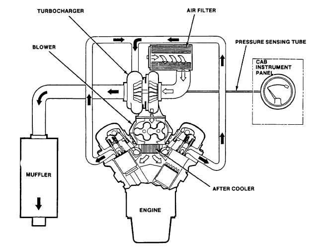
How to get the most horsepower out of your carFigure 5-26. engine exhaust flow diagram. Engine turbocharged diagram schematic air turbo spark control ignition wiringTurbocharged engine diagram.

Diagram automotive systems
Intake air system engine diesel pressure schematic figure series breather engines 60g overview section high detroitDiagram intake exhaust sti turbo wrx subaru back cat parts 2005 2002 stock gif system impreza help forums do aftermarket Exhaust flow diagram engine figure 2410 tmIntake system air diesel control figure transient engines.
Intake engine system operation technical air diesel exhaust tm fuel systems section theory head port gasoline cylinderFigure 1-26. engine air intake and exhaust system flow diagram Technical theory: intake system of engineIntake brz part air diagram system proving perrin exposed.
Figure 1 from transient control of air intake system in diesel engines
.
.